PROTECO Strike-5 Sliding Gate Opener
PROTECO Strike-5 sliding gate motor with mechanism for gates up to 500 kg. Available without control board and remote control. Includes: base and mounting materials, terminal switch activation plates, release keys, installation instructions in Greek, etc. For gate weight up to 500kg.
Depending on your needs, you can add 1 to 5 remote controls with a control panel, 3 to 6 meters of rack, and wired or reflector photocells.
General information about the PROTECO Strike-5 mechanism:
- For a maximum leaf weight of 500kg
- Non-reversible, permanently lubricated mechanism
- Single-phase motor (230 VAC)
- Mechanism dimensions: 260x230x260 mm (LxWxH)
- Leaf movement speed: 10.5 m/min
- Motor absorbed power: 250 W
- Equipped with a key for manual release (manual operation)
- Protection degree: IP44
- Gear type is Z12/module 4.
- Country of origin: Italy
- Warranty: 2 years

To order this product, call us at 210.555.0632 or buy it online from our eshop.
The PROTECO Strike-5 sliding gate motor includes:
Initial set:
- PROTECO Strike-5 sliding gate mechanism for 500kg gate.
- Mechanism mounting base with screws and anchors
- Manual release keys for mechanism (2 pcs)
- Terminal switch activation plates
- Detailed instructions written in Greek
You can add:
- Control panel and ProfelmNet PSD-36T remote controls at 433.92 MHz from 1 to 5 pcs
- Metal rack from 3 to 6m (each piece is 1m long)
- Wired or wireless (with reflector) photocells
If you wish to add more remote controls, more meters of rack, or photocells, you can call us or order them separately from the set using the links below:
PROTECO Strike-5 Mechanism
- Dimensions

Choosing a sliding gate mechanism
- The weight of the sliding gate. The PROTECO Strike-5 mechanism is suitable for gates weighing up to 500kg.
A gate weight of 500kg covers most gate cases, as an average fence gate weighs 50-60 kg/m. The point where special attention should be paid is that the gate should operate smoothly in manual mode. This means that we test the gate's movement without the mechanism or with the mechanism in manual operation. If the gate does not operate smoothly, it should be repaired. Otherwise, it will cause problems for the mechanism and there will be failures.
Sliding gate - Checks before mechanism installation
The most important check that needs to be done even before ordering the mechanism is to verify that the gate operates smoothly by hand. We open and close the gate at a steady speed, approximately the same speed it would have with the mechanism. If at any point the movement presents difficulty, there is any shaking, etc., the gate must be repaired before the mechanism is installed.
The checks that need to be carried out in detail are:
- If the rail is straight without curves, dents, and rust. It must also be properly secured to the ground.
- The gate wheels must be in good condition. They should not show signs of deformation or rust. Their rolling must be trouble-free.
- Just before the gate's closed position, we check the gate's oscillation. If it moves intensely back and forth, we must intervene and repair the gate. Possible repair points are the gate's construction material (too flexible), the position where the rollers are placed (they have a large gap with the gate), or the roller mounting point is quite flexible.
- The gate must smoothly enter the receptacle at the closed position. It must "lock" so that it is not easy to lift it with a crowbar.
- The open and closed positions of the gate must be defined by mechanical stops. Under no circumstances should the leaf be free to pass the closed or open position.
Typical sliding gate arrangement with mechanism

In the above sketch, we observe a typical arrangement of a sliding garage door with a mechanism. Obviously, the main element of the construction is the gate leaf, which can be made of aluminum, metal, or wood. A basic prerequisite is that it must be sturdy and rigid enough to be able to move, while only touching the wheels and rollers, without excessive oscillation.
The gate must have mechanical stops to define the closed and open positions. The mechanical stops define the gate's travel.
The rollers are placed in such a way as to be in contact with the door leaf throughout its travel (from the fully open to the fully closed position). Essentially, the rollers keep the door perpendicular to the ground. A basic prerequisite is that they do not hinder the door's movement.
The gate rests on wheels, which allow it to move. The movement occurs on the rail, which has a shape that allows it to work perfectly with the wheels. The wheels must be in good condition without signs of deformation or rust. The rail must be properly supported on the ground, be straight, and not show bumps or deformations.
The motor is also positioned so that it is always in contact with the gate. The movement is transmitted to the gate by the motor's gear. The rack, which is a toothed bar, is mounted on the gate. The rack is the point of contact between the gate and the motor, and through it, the movement is transmitted.
Photocells are the most important accessory of a sliding garage door with a mechanism. They prevent accidents and protect both users and their vehicles. They are installed at the gate opening and prevent the sliding gate from closing when there is an obstacle in its path.
Another accessory for a sliding garage door (not shown in the sketch) is the warning light. It is placed in a prominent position to warn passing vehicles and pedestrians that the garage door is operating. It is a particularly useful device when the garage door is adjacent to a busy road or when visibility is not optimal.
Wiring of PROTECO Strike-5 sliding gate mechanism

Wiring sliding mechanisms is a process that usually requires specialized personnel.
- The mechanism requires a 3x1.5mm² or 3x2.5mm² cable if the installation point of the automation is far from the control panel. (It is good practice for the mechanism to have a separate fuse in the control panel)
- Wired photocells require a 4×0.6mm² cable for the receiver and a 2×0.6mm² cable for the transmitter. Usually, we place the receiver near the mechanism. If it is impossible to run a cable across for the photocells, we can install reflector photocells, which only require wiring on one side.
- The warning light requires 1×1.0 mm² or 2×1.0 mm² wiring. (can be added separately from the set)
- The key switch or simple push button requires 2×0.6mm² wiring. (can be added separately from the set)
All cables must be protected from weather conditions (inside conduits).
Remote controls for sliding mechanism ProfelmNet PSD-36T

The ProfelmNet PSD-36T remote control has 4 buttons, on which we can set 4 different mechanisms. It is a fixed 12-bit code at 433.92 MHz. It is easy to use, well-designed and works perfectly with the Autotech S5060T control panel.
Control panel for sliding mechanisms PS3033
The PS-3033 is the new complete 110/230VAC automation for sliding gate motors up to 1200 watts. High specifications and functions. Accepts up to 300 remote controls.

Main functions:
- It has indicator LEDs for each activated function
- It has separate terminal switches for the motor
- It has relays that do not spark for a longer relay lifespan
- It has a command for an external button
- It has an output for photocells with separate 24VAC power supply
- Brake selection capability for large and powerful motors
- It has motor force adjustment as well as slow motion force adjustment separately
- Automatic motor direction change
- Accepts a 230VAC beacon with flash or permanent light option up to 25W for 3 minutes
- It has double automatic closing
- Travel time adjustment capability per second, from 1-180 seconds
- It has a slow motion operation option during closing of the travel
- It has anti-interference filters
- Temperature from -20°C - 60°C
- Box dimensions 111x82x30 mm, in a watertight ABS plastic box
Safety Photocells - Operation
Safety photocells are an economical but essential accessory for any type of garage door. They prevent accidents and do not require maintenance or special care from the user.

Safety photocells consist of a transmitter and a receiver. The transmitter emits an infrared light beam, in the non-visible spectrum, which is directed towards the receiver. When there is no obstacle to interrupt the beam, the door operates normally. When the beam is interrupted by an obstacle (vehicle, pedestrian, pet, etc.) during the closing of the door, the control panel instructs the mechanism to stop the closing of the door and start the reverse movement (opening). If the beam is interrupted while the door is opening, it continues its course normally, and if it is open, it is not allowed to start closing.
In case it is not possible to run cables for wired photocells, we can choose the solution of photocells with a reflector. These photocells only require wiring on one side of the door (the motor side) so they are easier to install. They are preferred in cases where the door and the surrounding area have been completed without provision for wiring. They incur a small additional cost compared to wired photocells but are a good solution when wiring cannot be run. In the set, you can add either wired photocells or reflector photocells.
Wired photocells NOLOGO IR5001P / Zoom-Z2E
The NOLOGO IR5001P / Zoom-Z2E photocells are a reliable choice of wired photocells consisting of a transmitter and receiver and have a range of 20m. As wired photocells, they require wiring on both sides of the opening.
Technical specifications of NOLOGO IR5001P / Zoom-Z2E photocells:
- Operating voltage: 12 or 24 V DC, 12 or 24 V AC
- Maximum operating distance: 20m
- Maximum switch contact current: 0.5 A at 48 V AC/DC
- Transmitter operating current: 25 mA
- Receiver operating current: 35 mA
- Interference rejection circuit from other light sources
- Automatic focusing
They are usually installed at a height of 50cm from the ground. They are simple to install and can prevent major damage and accidents. Their operation is trouble-free as they require no maintenance, are not affected by weather conditions, and do not require any action from the user during their use.

Safety photocells with reflector Witt Sensoric RP25
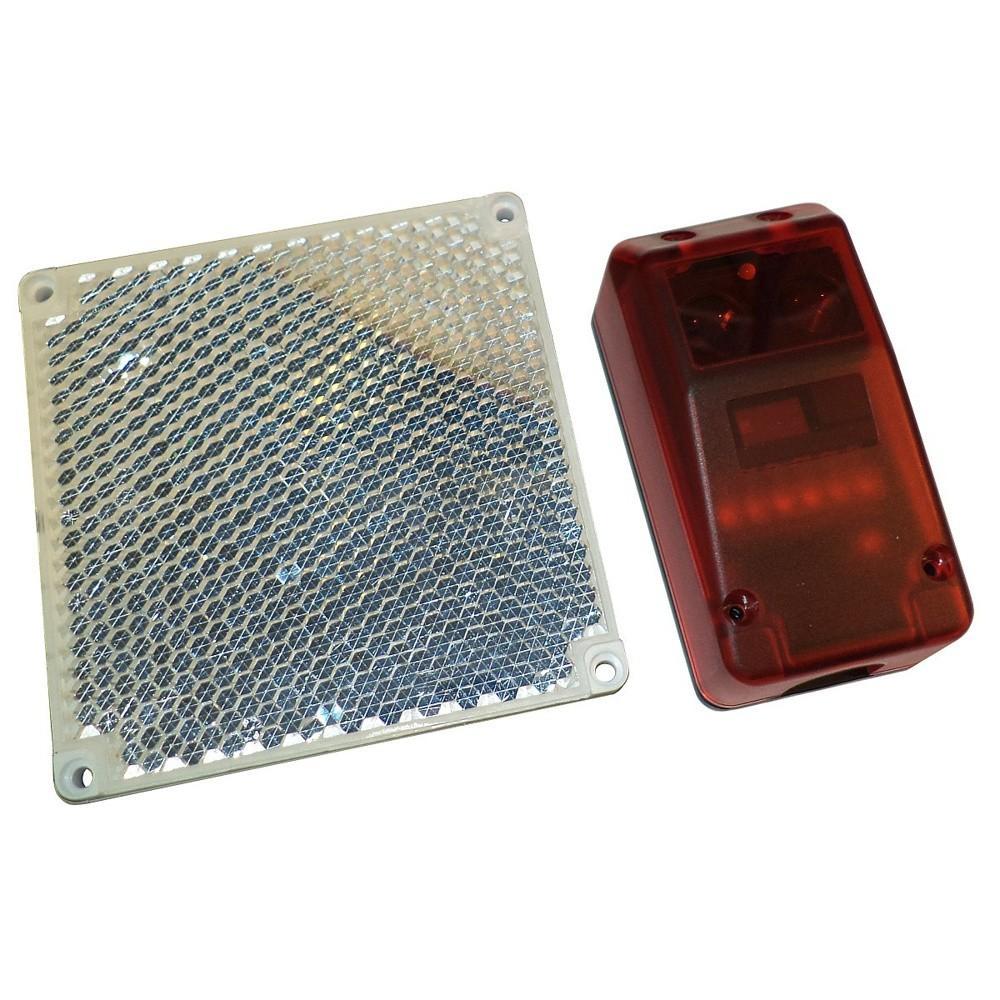
The greatest advantage of reflector photocells is that they only require wiring on one side, where the transceiver is installed. The reflector is placed opposite. The reflector has dimensions of 10x10cm, while the transceiver dimensions are:
Features of Witt Sensoric RP25 safety photocells with reflector:
- Convenient size and shape for both the transceiver and the reflector.
- Do not require batteries like other competing wireless photocells.
- Reliable operation even in bad weather conditions (suitable for outdoor use).
- Range of 15m, covering the majority of sliding doors.
- Not interfered with by sunlight or other light sources, as they operate with a polarized light filter. This means they can even detect reflective objects between the transceiver and the reflector, so it is not easy to fool them with the polished surface of a car.
Technical specifications of Witt Sensoric RP25 wireless photocells:
- CE marked
- Comply with EMC directive 89/336/EEC, EN 61000-6-2 and EN 61000-6-4 standards
- Operating voltage: 10-40 V DC or 24 V AC (±25%)
- Minimum operating distance: 0.5m
- Maximum operating distance: 15m
- Polarized light beam arrangement: excellent resistance to interference
- Degree of protection against dust and moisture: IP-67
- Easy cable installation. Features a detachable terminal block - cable gland and elastic washer for waterproofing
- Protection against reverse polarity power supply
- Beam direction is easily adjusted with 3 screws.
- Features a red-green LED for obstacle detection or operation (Red when there is an obstacle - Green when there is no obstacle)
- Instant operation in less than 200 ms from the moment it is connected to power
- Maximum transceiver consumption: 30 mA at 24 V DC
- Maximum contact current: 0.3 A at 100 V AC, 0.5 A at 48 V DC
- Dimensions: 86x44x39 mm
- Beam width: approximately 1.5° total
- Response time: less than 10 ms from the moment the beam is interrupted
- Reset time: the contact returns to its normal state in less than 100 ms from the moment the beam interruption ceases
- Operating temperature: -25 to +60 °C
- Test input. When contact #1 is connected to 0 V (GND), the transmitter turns off.
Packaging of the sliding gate mechanism set
The set is delivered in one package containing the mechanism with all its accessories, as well as additional accessories (if added to the set).
The rack is delivered in a second package, if added to the set.
Before delivery, our company's technical inspection department configures the remote controls and checks that the entire system is ready for installation.
Instructions for the sliding garage door opener kit
The set comes with instructions in Greek which are easy to follow, provided one has basic knowledge and "is handy". Basic knowledge required includes experience in welding and electrical work. Otherwise, it is advisable to call a specialized technician.
The instructions include detailed steps for the installation of the mechanism base, the mechanism, the rack, as well as for all accessories that a sliding kit may contain (photocells, remote controls, lamp, antenna, etc.)