

RIB K1400 Sliding Gate Motor
Set for sliding garage door with RIB K1400 mechanism for up to 1400 kg gate and 400 openings/closings per day. Included: base and mounting materials, limit switch tabs, disengagement keys and Greek installation instructions.
Available in its basic version without control panel, without remote control. Depending on your needs, you can add 1 to 5 remote controls with a control panel, 5 to 8 meters of rack, and wired or reflective photocells.
General information about the RIB K1400 mechanism:
- For a maximum gate leaf weight of 1400kg.
- Non-reversible, permanent lubrication mechanism
- Maximum frequency of use: S3-70% at 20°C
- Up to 50 openings/closings per hour
- Up to 400 openings/closings per day
- Single-phase motor (230 VAC)
- Mechanism dimensions: 303x296x320 mm (LxWxH)
- Gate leaf movement speed: 9.6 m/min
- Motor absorbed power: 257 W
- Equipped with a key for disengagement (manual operation)
- Protection degree: IP44
- Gear type is Z17/module 4
- Country of origin: Italy
- Warranty: 2 years
To order this product, call us at 210.555.0632 or buy it online from our e-shop.
RIB K1400 Mechanism - Dimensions

Choosing a sliding garage door mechanism
- The weight of the sliding garage door. The RIB K1400 mechanism is suitable for doors weighing up to 1400kg.
- The frequency of daily use of the door. The RIB K1400 mechanism is suitable for up to 400 openings/closings per day.
- The frequency of door use per hour. The RIB K1400 mechanism is suitable for up to 50 openings/closings per hour.
The RIB K1400 mechanism has an advantage over the competition due to its ability to operate intensively. Even large residential complexes during peak hours are unlikely to have more than 50 openings/closings per hour (this corresponds to approximately one vehicle every two minutes). Also, 400 openings/closings per day are enough that a sliding garage door would hardly exceed them, even in a professional setting.
Finally, the 1400kg door covers most door cases, as an average gate weighs 50-60 kg/m. Particular attention should be paid to ensuring that the door operates smoothly in manual mode. This means testing the door's rolling without the mechanism or with the mechanism in manual operation. If the door does not operate smoothly, it should be repaired before installing the mechanism. Otherwise, it will cause problems with the mechanism and lead to breakdowns.
Sliding garage door - Checks before mechanism installation
The most important check that needs to be done even before ordering the mechanism is to verify that the door operates smoothly by hand. Open and close the door at a steady speed, similar to what it would have with the mechanism. If at any point the movement presents difficulty, there is a jolt, etc., the door must be repaired before installing the mechanism.
The checks that need to be carried out in detail are:
- If the rail is straight without bends, dents, and rust. It must also be properly secured to the ground.
- The door's wheels must be in good condition. They should not show signs of deformation or rust. Their rolling must be problem-free.
- Just before the door's closed position, check the door's oscillation. If it moves excessively back and forth, we must intervene and repair the door. Possible repair points are the door's construction material (excessively flexible), the position where the rollers are installed (they have a large gap with the door), or the roller support point is quite flexible.
- The door must smoothly enter the recess at the closed position. It must "lock in" so that it cannot be easily lifted with a crowbar.
- The open and closed positions of the door must be defined by mechanical stops. Under no circumstances should the gate leaf be free to pass the closed or open position.
Typical sliding garage door setup with mechanism

In the sketch above, we observe a typical arrangement of a sliding garage door with a mechanism. Obviously, a key component of the construction is the gate leaf, which can be made of aluminum, metal, or wood. A basic prerequisite is that it must be sturdy and rigid enough to move, while only touching the wheels and rollers, without excessive oscillation.
The door must have mechanical stops to define the closed and open positions. The mechanical stops define the door's travel.
The rollers are placed at a point where they are in contact with the gate leaf throughout its entire travel (from the fully open to the fully closed position). Essentially, the rollers keep the door perpendicular to the ground. A basic prerequisite is that they do not hinder the door's movement.
The door rests on the wheels which allow it to move. The movement takes place on the rail, which is shaped to work perfectly with the wheels. The wheels must be in good condition, without signs of deformation or rust. The rail must be properly supported on the ground, be straight, and not show bumps or deformations.
The motor is also placed at a point where it is always in contact with the door. The movement is transmitted to the door by the motor's gear. The rack, which is a toothed bar, is placed on the door. The rack is the point of contact between the door and the motor, and through it, the movement is transmitted.
Photocells are the most important accessory of a sliding garage door with a mechanism. They prevent accidents and protect both users and their vehicles. They are placed at the door's opening and prevent the sliding door from closing when there is an obstacle in its path.
Another accessory for a sliding garage door (not shown in the sketch) is the warning light. It is placed in a prominent position to warn passing vehicles and pedestrians that the garage door is in operation. This is a particularly useful device when the garage door is adjacent to a busy road or when visibility is not optimal.
Installation of RIB K1400 sliding mechanism
The rack spacers usually allow for fine adjustments of about 0.5cm. In case the door is hollow at the height where the rack needs to be installed, without any support point, we have two options. Either reinforce the door at that point or change the installation height of the mechanism (with a base) to reach the point where the rack can be installed.
In addition to the above limits for the installation of the mechanism, we must take into account that:
- it should not be placed in an area where water accumulates. If there is such a suspicion, a base must be created so that the motor is higher.
- the gate leaf should be approximately 40cm longer than the opening to allow the motor to be installed outside the opening. Otherwise, there is a risk of the motor being hit by a passing vehicle.
- the base must be placed on a stable substrate. If such is not available (e.g., a reinforced concrete slab), a concrete base must be created.
Next, we define the position of the accessories. If there are photocells, a warning light, etc., we define their position and then proceed with the wiring. There will be a detailed chapter on wiring below. We simply mention that it should be done by a professional electrician and in compliance with all safety regulations.

When installing the base, we check that it is perfectly parallel to the door. We also check with a spirit level that it is perfectly horizontal. The large hole in the base is for routing cables. The base is mounted with plugs (metal anchors) in the reinforced concrete.
Next, we remove the mechanism's cover. To remove it, unscrew the corresponding screws. We secure the mechanism to the two screws protruding from the base. We place it on the base and tighten the screws.

To operate the mechanism manually, lift the flap, insert the key into the lock, and turn it counter-clockwise as many turns as necessary until the key stops. In this position, the motor has been disengaged, and we leave it in this state until the rack installation is complete.
Point of attention: Before welding, disconnect the terminals from the control panel.
The metal rack consists of one-meter pieces. Each piece has three oval-shaped holes where the spacers are placed.

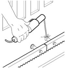
It is advisable to screw the spacers in the middle of the holes so that micro-adjustments can be made later if necessary. As we can see in the diagram above, there is a wide side of the spacer (shoulder) which is welded onto the door. The main point of attention during the rack installation is the small gap that must exist between the gear and the rack.

This gap helps the door operate correctly. If it is not present, the motor is forced to carry the door, so at some point, it will inevitably wear out and develop a fault. If the gap is too large, the gear may "kick" and the door's movement may not be correct. In both cases, it is possible that a problem may arise with either the door or the motor.
The correct gap is around 1.5 mm. To achieve this, we can place the mechanism on a surface of this thickness and proceed with the installation of the rack with contact to the gear. Then, after removing this surface, the motor will move down by 1.5mm, thus providing the necessary gap.
During the installation of the rack, we must not weld the pieces of the rack together and must maintain its pitch. Also, the rack must not be welded to the spacers. The following diagram shows exactly the procedure that must be followed.

We must also ensure that the gear engages with the rack throughout its entire travel. If necessary, we can loosen the mechanism's mounting and move it perpendicularly to the gate leaf to achieve the correct position.
The necessary check for the correct installation of the rack is done by opening and closing the door at a steady speed. If the door moves smoothly without jolts, noises, etc., then the rack installation is correct. Then we can tighten the screws of the spacers as well as the mounting screws of the motor.
Point of attention: Before operating the mechanism electrically, we must first confirm the opening direction (it must be correct) and install the limit switches.
 Next, the limit switches, which are included in the mechanism set, are installed. Under no circumstances should makeshift limit switches be used or their shape modified, as this will cause the mechanism to malfunction. The limit switches are placed at such a point that they activate the mechanism's limit switches. This is done by pushing the spring-loaded rod of the mechanism in one direction or the other. Particular attention is required so that the door stops 2cm before the final position, both in the open and closed positions. In this way, the door will not hit any of the fixed points at the end of its travel.
- Check that the wiring in the control panel is correct (the direction must be correct for right-left).
- Manually push the door left and right and check that the corresponding LED for the open and closed position turns off. Check that there is the correct distance (approximately 2cm) from the open and closed stop positions, respectively.
Finally, a good functioning check of the entire installation is essential. We check if the door stops at the correct points, if the photocells are working, if the remote controls work correctly, etc. It is advisable to perform the above checks at least twice a year.
Then we hand over the remote controls to the users and inform everyone involved with the garage door (users and non-users) about its operation and points of attention during its use.
RIB K1400 sliding garage door mechanism gear
 The RIB K1400 mechanism features a metal gear surrounded by a protective cover to prevent injuries.
Wiring of RIB K1400 sliding garage door mechanism

Wiring for sliding mechanisms is a procedure that usually requires specialized personnel.
- The mechanism requires a 3x1.5mm² or 3x2.5mm² cable if the distance of the automation installation point is far from the control panel. (It is advisable that the mechanism in the control panel has a separate fuse)
- Wired photocells require a 4×0.6mm² cable for the receiver and a 2×0.6mm² cable for the transmitter. We usually place the receiver near the mechanism. In case it is impossible to route a cable across for the photocells, we can install photocells with a reflector, which only require wiring from one side.
- The warning light requires 1×1.0 mm² or 2×1.0 mm² wiring.
- The key switch or simple push button requires 2×0.6mm² wiring.
All cables must be protected from weather conditions (inside conduits).
Sliding mechanism control panel

The Autotech S5060T control panel is included in the set and integrated into the mechanism. It is a control panel that combines simplicity of use with all necessary functions and has been time-tested. It works perfectly with the RIB K1400 mechanism.
Technical characteristics:
- It has a socket for the mechanism's limit switches
- We can adjust the mechanism's force.
- There is the possibility for soft start and stop for less wear and tear on the mechanism and the garage door.
- It accepts safety photocells that interrupt movement when they encounter an obstacle during door closing and initiate reverse movement (opening).
- There is an available setting for automatic door closing with the user's choice of closing start time. The use of photocells is essential for automatic closing to function.
- There is an option for electric braking.
- The opening direction is adjusted with a microswitch.
- The panel can accept push buttons (keypad or simple push button).
- The panel can accept a 230VAC warning light without a flasher or a 230VAC lighting lamp.
- It has a built-in receiver with simple operation.
- User information regarding the mechanism's functions is provided by LED lights.
The above control panel has been tested by thousands of users and has proven to be extremely reliable. Additionally, it features functions such as adjusting the mechanism's force, slow start, and stop, which make it one of the best choices on the market today.
ProfelmNet PSD-36T sliding mechanism remote controls

The ProfelmNet PSD-36T remote control has 4 buttons on which we can set 4 different mechanisms. It has a fixed 12-bit code at 433.92 MHz. It is easy to use, well-designed, and works perfectly with the Autotech S5060T control panel.
Packaging of the sliding garage door mechanism set
The set is delivered in two separate packages if it contains a metal rack. The elongated package contains the metal rack. The second package contains the mechanism with all its accessories, as well as the accessories.
Before delivery, our company's technical inspection department sets up the remote controls and checks that the entire system is ready for installation.
Instructions for the sliding garage door mechanism set
The kit comes with easy-to-follow instructions in Greek, provided one has basic knowledge and is "handy". Basic knowledge required includes experience in arc welding and electrical work. Otherwise, it is advisable to call a specialized technician.
The instructions include detailed steps for installing the mechanism's base, the mechanism itself, the rack, as well as all accessories that a sliding gate kit may contain (photocells, remote controls, beacon, antenna, etc.)