

Motor for Sectional Garage Doors Motorline Professional LINCE 600
Depending on your needs, 1 to 4 remote controls and wired or reflector photocells can be added to a single or double leaf swing gate operator Motorline Professional LINCE 600. General information for the left-hand LINCE 600 operator:
- Electromechanical operator with permanent lubrication
- Maximum door leaf width (with electric lock): up to 4.0 m
- Maximum door leaf width (without electric lock): up to 2.5 m
- Maximum number of operating cycles per hour: up to 21 at 20°C
- Maximum number of operating cycles per day: up to 30
- Piston stroke (useful): 60 cm
- Maximum force: 2300 N
- Single-phase motor. Motor operating voltage: 230 VAC
- Motor absorbed power: 2X180 W
- Motor winding thermal protection: 120 °C
- Manual release with special hexagonal key
- Warranty: 2 years
To order this product and customize it to your needs, call us at 210.555.0632 or buy it online from our e-shop.
LINCE 600 Operator - Dimensions

Motorline Professional LINCE 600 motors have convenient dimensions and a beautiful design.
Visual checks during swing gate operator installation
The first point of inspection during the installation of a swing gate operator is whether there is space for the arm. Open the door 90o and observe if there is space for the operator behind it. If the door abuts a structural element or another obstacle (like the left leaf in the diagram below), then an operator cannot be installed without modifying the door or creating the appropriate space. (in this case, excavating the structural element and creating space for the motor)
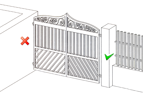
Depending on the user's needs, the gate can be of an open or closed type. Open-type gates allow visibility and air passage, as they are usually designed with railings. In contrast, closed-type gates do not allow visibility to and from the area and, of course, no air passage. This often makes movement difficult as wind pressure exerts great forces on the gate and consequently on the operator. Therefore, in areas with strong winds, it is incorrect to install an operator on a solid swing gate. In the best case, the gate will not operate correctly (it will partially close) when there is wind pressure, and there is a high probability that the operator will be damaged.
This point requires particular attention as no manufacturer's warranty covers damage due to wind pressure. In many cases, we could achieve better gate performance by installing a stronger operator and/or an electric lock. However, in most cases, our advice is not to install a swing gate operator on a solid gate unless it is protected from strong wind pressures. (e.g., in densely populated areas, if there is a tall building in front, etc.). The following sketches illustrate single and double leaf gates:


- It must operate correctly manually.
- It must have a mechanical stop.


Swing gate operator installation distances - Operating modes
Swing gate operators can operate in 2 ways:
1st way: They pull the gate to open it and push it to close it. (opening inwards)
2nd way: They push the gate to open it and pull it to close it. (opening outwards)
The distances 'X' and 'Y' for the operator mounting position must comply with the following tables and diagrams for both installation methods.
1st way:

|
FOR OPENING 950 TOWARDS THE INSIDE |
X (in mm) |
Y (in mm) |
|
MECHANISM with 400mm stroke |
120 to 180 |
120 to 180 |
|
MECHANISM with 600mm stroke |
120 to 350 |
120 to 200 |
2nd way:

|
FOR OPENING 950 TOWARDS THE OUTSIDE |
X (in mm) |
Y (in mm) |
|
MECHANISM with 400mm stroke |
160 to 200 |
120 to 180 |
|
MECHANISM with 600mm stroke |
160 to 300 |
120 to 280 |
Single-leaf swing garage door - Wiring

- (1) The operator requires a 3x1.5mm² or 3x2.5mm² cable if the installation point of the automation is far from the control panel. (it is advisable for the operator to be on a separate fuse in the control panel) The cable must be waterproof and in a pipe with a cross-section of at least Φ16. The provision left by the electrician must be sufficient (1.5m) to reach the installation point of the electronic control panel.
- (2) Wired photocells require a 4×0.6mm² cable for the receiver and a 2×0.6mm² cable for the transmitter. Usually, we place the receiver near the operator and the panel. If it is impossible to route a cable across for the photocells, we can install reflector photocells which only require wiring on one side. (so line 2 is not required)
Remarks:
- A single or double leaf gate requires one control panel.
- Heliflex type flexible PVC plastic pipes are most suitable for this type of installation.
- Wiring must be protected and watertight to prevent short circuits, etc.
Double-leaf swing garage door - Wiring

- (1) The operator requires a 4x1.5mm² or 4x2.5mm² cable if the installation point of the automation is far from the control panel. (it is advisable for the operator to be on a separate fuse in the control panel) The cable must be waterproof and in a pipe with a cross-section of at least Φ16. The provision left by the electrician must be sufficient (1.5m) to reach the installation point of the electronic control panel.
- (2) Wired photocells require a 4×0.6mm² cable for the receiver and a 2×0.6mm² cable for the transmitter. Usually, we place the receiver near the operator and the panel. If it is impossible to route a cable across for the photocells, we can install reflector photocells which only require wiring on one side. (so line 2 is not required)
- (4) For a push button (or key switch), a 2x0.5mm² cable is required (not included in the set).
- (5) The remote control receiver requires a 3x0.5mm² cable (in our case, it is integrated into the panel).
- (6) The safety beacon requires a 2x1.5mm² cable (not included in the set).
- (7) The electric lock requires a 2x1.5mm² cable (not included in the set).
Remarks:
- A single or double leaf gate requires one control panel.
- Heliflex type flexible PVC plastic pipes are most suitable for this type of installation.
- Wiring must be protected and watertight to prevent short circuits, etc.
ProfelmNet PSD-36T remote controls for swing operators
You can add up to 5 ProfelmNet PSD-36T remote controls at 433.92 MHz to the swing operator kits (if you require more, please contact us by phone or email). The ProfelmNet PSD-36T remote controls are user-friendly, practical, and functional. They can store up to 4 gates. They have a 12-bit fixed code at 433.92 MHz. They can copy remote controls of the same type, as well as older fixed-code remote controls operating at 433.92 MHz.

ProfelmNet PS-3114 control board for Lince 600 operator

ProfelmNet PS-3114 control board (with enclosure) for 230 VAC swing garage door motors. Suitable for single or double leaf gates.
- Single-phase motor (230 VAC).
- Operating frequency: 433.92 MHz.
- Integrated 433.92 MHz receiver with easy remote control registration.
- Encoding: Fixed
- Motor force adjustment.
- Slow motion adjustment.
- Automatic closing activation.
- Inputs for safety devices such as safety photocells (supports photocells for protection during closing and photocells for protection during closing and opening).
- Push-button inputs for opening/closing command.
- Output for 230VAC warning light or lighting.
- Ability to add an electric lock.
- Easy learning of travel time with learning of opening, closing, slow speed during opening, slow speed during closing for each motor separately.
- Diagnostic LEDs for the operating status of each motor.
- CE Compliance
Note that electrical connections and travel programming must be done as described in the respective panel instructions to avoid problems during the operator's operation.
Detailed instructions for ProfelmNet PS-3114 remote control panel
Manual release of Lince 600 swing operator
Steps for manual release of the swing operator:
Unclip the protective cover:

Check the special marking for the opening direction:


Detailed description of NOLOGO IR5001P / Zoom-Z2E wired photocells
- Operating voltage: 12 or 24 V DC, 12 or 24 V AC
- Maximum operating distance: 20m
- Maximum current of switch contacts: 0.5 A at 48 V AC/DC
- Transmitter operating current: 25 mA
- Receiver operating current: 35 mA
- Interference rejection circuit from other light sources
- Automatic focusing

Description of Witt Sensoric RP25 reflector safety photocells


- In addition to not requiring wiring, they also do not require batteries like other wireless photocells. This practically means that the user installs them and does not have to deal with them again.
- The large reflective surface of the reflector makes their operation more reliable.
- The design of the Witt Sensoric RP25 photocells is suitable for outdoor use, making them suitable for use on garage doors.
- They have a range of 15m, making them suitable for most garage doors/gates.
- They are not interfered with by sunlight or other light sources because they operate with a polarized light filter. This means they can even detect reflective objects between the transceiver and the reflector, so they are not easily fooled by the polished surface of a car.
Technical specifications:
- CE marked
- Comply with EMC directive 89/336/EEC, EN 61000-6-2 and EN 61000-6-4 standards
- Operating voltage: 10-40 V DC or 24 V AC (±25%)
- Minimum operating distance: 0.5m
- Maximum operating distance: 15m
- Polarized light beam arrangement: excellent interference immunity
- Protection degree against dust and moisture: IP-67
- Easy cable installation. Features a detachable terminal block - cable gland and a rubber washer for sealing
- Protection against wrong polarity power supply
- Beam direction is easily adjusted by 3 screws.
- Features a red-green LED for obstacle detection or operation (Red when there is an obstacle - Green when there is no obstacle)
- Immediate operation in less than 200 ms from the moment it is connected to power
- Maximum transceiver consumption: 30 mA at 24 V DC
- Maximum contact current: 0.3 A at 100 V AC, 0.5 A at 48 V DC
- Dimensions: 86x44x39 mm
- Beam range: approx. 1.5° total
- Response time: less than 10 ms from the moment the beam is interrupted
- Reset time: the contact returns to its normal state in less than 100 ms from the moment the beam interruption ceases
- Operating temperature: -25 to +60 °C
- Test input. When contact #1 is connected to 0 V (GND), the transmitter turns off.
Lince 600 Mechanism Installation Instructions
The set is delivered with instructions in Greek which are easy to follow provided one has basic knowledge and is "handy". Otherwise, it is advisable to call a specialized technician.
The instructions include detailed steps for the installation of the mechanism base, the mechanism itself, and all accessories that an opening set may contain (photocells, remote controls, lamp, antenna, etc.)
Instructions in English for the motor can be found at the following link: Lince 600 Mechanism Instructions EN