

LINCE 600 single-leaf hinged garage door operator kit right (Kit-Standard-2114)
An economical, complete kit for a single-leaf right-hand swing garage door mechanism, which includes: a LINCE 600 motor (right), a ProfelmNet 2114 control board in a waterproof plastic box, a set of wired safety photocells, and two remote controls.
- Electromechanical mechanism with permanent lubrication
- Maximum door leaf width (with electric lock): up to 4.0 m
- Maximum door leaf width (without electric lock): up to 2.5 m
- Maximum number of operating cycles per hour: up to 21 at 20°C
- Maximum number of operating cycles per day: up to 30
- Piston stroke (useful): 60 cm
- Maximum force: 2300 N
- Single-phase motor. Motor operating voltage: 230 VAC
- Motor absorbed power: 2X180 W
- Motor winding thermal protection: 120 °C
- Manual override with special hexagonal key
- Warranty: 2 years
To order this product, please call us at 210.555.0632 or buy it online from our e-shop.
Contents of the LINCE 600 right-hand kit (Kit-Standard-2114)

- LINCE 600 mechanism (right-hand)
- ProfelmNet PS-2114N control board mounted in a waterproof box, 1 pc
- 2 ProfelmNet PSD-36T remote controls at 433.92 MHz with 4 buttons
- 1 set of wired photocells
- All necessary accessories for the installation and operation of the mechanism (mounting brackets and screws for the motor, capacitor, 1 release key and installation instructions)
Manufactured by the Portuguese company Electrocelos, known for the reliability and durability of its products.
The LINCE 600 mechanism can move door leaves up to 2.5m wide without an electric lock and up to 4.0m wide with an electric lock.
The above kit can be installed for the automation of a single-leaf swing garage door. Depending on your needs, additional products can be added to the kit, such as remote controls, photocells, etc.
LINCE 600 Mechanism - Dimensions

Mechanism with very convenient dimensions, suitable for most swing gates.
Installation of a Swing Gate Mechanism - Specifications
Installing a swing gate mechanism is a relatively simple matter, provided that due attention is paid to certain specific dimensions. These dimensions are as follows:
- The width of the door leaf WR.
- The distances CR & DR. These dimensions are important when the mechanism is installed on the same side from which the door opens. (Conversely, when the door opens outwards and the mechanism is inside, or vice versa, these dimensions do not play a role, but the clear passage width is reduced.)
- The maximum number of door openings and closings per day and per hour.
- The design of the door. What interests us in the design is whether it allows air to pass through without resistance. That is, a wrought-iron gate is the best case, while a solid door without gaps is certainly a door that can face problems when strong winds prevail.
Our company is always ready to help you choose the right mechanism for your gate. You can contact us by phone or email, and we will guide you in choosing the motor for your gate. It is essential to know the above information, and in case of sending an email, photos of the gate and the installation point of the mechanism would facilitate our selection.
Analysis of Critical Dimensions for Choosing a Swing Gate Mechanism
WR: width of the gate
CR: we open the door 90o and measure the distance perpendicular to the door from a possible obstacle (structural element, tree, etc.)
DR: We measure perpendicular to the closed door the distance from the installation point of the mechanism's base to the point where the door hinge is located.

We measure the distances from the center of the hinge for greater accuracy:

Visual checks during swing gate mechanism installation
The first point of inspection during the installation of a swing mechanism is whether there is space for the arm. We open the door 90o and observe if there is space behind it for the mechanism. If the door abuts a structural element or another obstacle (such as the right leaf in the diagram below), then a mechanism cannot be installed without modifying the door or creating the appropriate space (in this specific case, excavating the structural element and creating space for the motor).

Depending on the user's needs, the gate can be of an open type or a closed type. Open types allow visibility and air passage, as they are usually designed with railings. In contrast, closed types do not allow visibility to and from the area and, of course, wind passage. This often makes movement difficult, as wind pressure exerts great forces on the gate and consequently on the mechanism. Therefore, in areas with strong winds, it is incorrect to install a swing mechanism on a solid swing gate. In the best case, the door will not function properly (it will only partially close) when there is wind pressure, and there is a high probability of the mechanism being damaged.
This point requires special attention, as no manufacturer's warranty covers damages caused by wind pressure. In many cases, we could have better door performance by installing a stronger mechanism and/or an electric lock. In most cases, however, our advice is not to install a swing mechanism on a solid gate unless it is protected from strong wind pressures (e.g., in densely populated areas, if there is a tall building in front, etc.).

Also, a basic prerequisite for installing a mechanism on a swing gate is that it operates perfectly manually and has mechanical stops.
Mechanical stops define the end of the door's travel in both the open and closed positions.

Installation Distances for Swing Mechanisms - Operating Modes
Swing mechanisms can operate in 2 ways:
1st way: They pull the gate to open it and push it to close it.
2nd way: They push the gate to open it and pull it to close it.
The following diagrams analyze the operating method of a swing gate. The gate rotates around an axis (H) defined by its hinges (from their center).
The motor is supported by 2 pivots:
- The first is fixed and is the attachment point of the mechanism to the structural element. (P1)
- The second is movable and is the attachment point of the mechanism to the gate. (P2)
These three points H, P1, P2 define a triangle with fixed sides H-P1 & H-P2 and one with variable length P1-P2. Depending on the installation method, the length P1-P2 increases when the door opens and decreases when it closes, or vice versa.
The distance from the center of rotation of the mechanism to the center of rotation of the gate (H-P1) determines the operation of the mechanism. This is defined by the distances X and Y, which are clearly distinguishable in the following diagram.
These distances are determined by the mechanism manufacturer and must be observed during installation. A detailed table with these distances follows below.
Also, to determine point P2, we follow this procedure: In the first installation method, after we have defined point P1, we define point P2 at a distance Le where the piston is extended almost to the end of its stroke. In the second installation method, after we have again defined point P1, we define point P2 at a distance Lc where the piston is retracted almost to the limit of its stroke.
Detailed diagrams and tables follow, where S2 and S1 are the stops for the open and closed positions respectively.
1st Installation Method for Swing Mechanism


This installation method is the most widespread and has the most advantages as it does not alter the design of the gate, the mechanisms are located indoors and thus protected, and the clear opening width remains as it was before the mechanism's installation. The only disadvantage is that specific spaces are required for the mechanism's placement.
2nd installation method for swing mechanism

This installation method is rarely used. The motor is placed between the opening and pushes the door to open it while pulling it to close it. It has advantages, the most significant being the possibility of installation even when the necessary spaces required for the first installation method are not available. Also, the mechanism does not alter the appearance of the door and is indoors, thus protected. Disadvantages of this method are that it reduces the clear passage width and that the door opens outwards, so there is a risk to passers-by, etc.
Single-leaf swing garage door - wiring
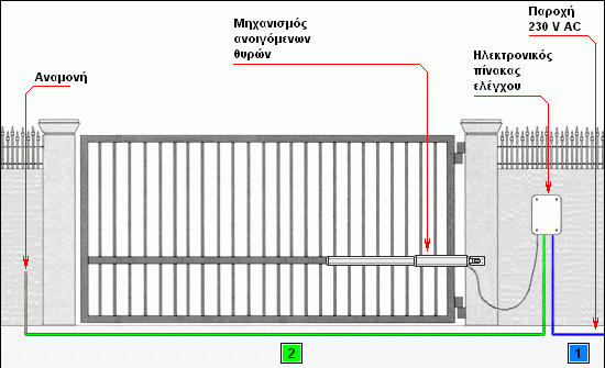
- (1) The mechanism requires a 3x1.5mm² or 3x2.5mm² cable if the installation point of the automation is far from the control panel. (It is advisable for the mechanism to be on a separate fuse on the control panel.) The cable must be waterproof and in a pipe with a minimum diameter of Φ16. The provision left by the electrician must be sufficient (1.5m) to reach the installation point of the electronic control panel.
- (2) Wired photocells require a 4×0.6mm² cable for the receiver and a 2×0.6mm² cable for the transmitter. We usually place the receiver near the mechanism and on the panel. If it is not possible to route a cable across for the photocells, we can install photocells with a reflector, which only require wiring on one side. (So, line 2 is not required.)
Observations:
- Single-leaf or double-leaf gate requires one control panel.
- Plastic flexible PVC pipes of the Heliflex type are most suitable for this type of installation.
- Wiring must be protected and watertight to prevent short circuits, etc.
Remote controls for swing mechanisms ProfelmNet PSD-36T

The ProfelmNet PSD-36T remote control has 4 buttons, which can be configured for 4 different mechanisms. It has a fixed 12-bit code at 433.92 MHz. It is easy to use, well-designed, and works perfectly with the control boards of swing mechanisms.
Wired photocells for the LINCE 600 right-hand kit (Kit-Standard-2114)

Safety photocells are a product that prevents accidents and damage at a small cost. If there is an obstacle between the transmitter and the receiver, they prevent the door from closing, thereby protecting pedestrians, vehicles, etc. If it is not possible to run cables to the opposite side, photocells with a reflector can be installed at a small extra cost.
Manual override of Lince 600 swing mechanism
Steps for manual override of the swing mechanism:
Unclip the protective cover:

Check the special marking for the opening direction:

Insert the manual override key:

Rotate the key 180ο as shown in the diagram below:

The manual override process is complete. The door can now be moved manually. To revert the mechanism to electrical operation, follow the reverse procedure.
Lince 600 Mechanism Installation Instructions
The kit is delivered with instructions in Greek that are easy to follow, provided one has basic knowledge and is "handy". Otherwise, it is advisable to call a specialized technician.
The instructions include detailed steps for the installation of the mechanism's base, the mechanism itself, as well as for all accessories that a swing kit may contain (photocells, remote controls, beacon, antenna, etc.)
Instructions in English for the motor can be found at the following link: Lince 600 EN Mechanism Instructions