NORTON FCM 400 Sliding Gate Motor
Features of the NORTON FCM 400 motor

- Suitable for doors with a maximum weight of 600kg
- Non-reversible, permanently lubricated mechanism
- Uses per hour: up to 12 (at 20°C)
- Uses per day: up to 30
- Single-phase motor (230 VAC)
- Mechanism dimensions: 230x210x230 mm (LxWxH)
- Door leaf speed: 10 m/min
- Motor absorbed power: 250 W
- Motor thermal protection: 120 °C
- Manual override (disengagement) with key access
- Protection degree: IP44
- Gear: Z12/module 4.
- Country of import: Italy
- Warranty: 2 years
Orders by phone 210.555.0632 or directly from our online eshop.
NORTON FCM 400 motor installation - Key selection criteria
- For doors with a maximum weight of 600kg.
- Maximum uses per hour: 12 openings/closings
- Maximum uses per day: 30 openings/closings
The door's weight can be up to 600kg, which means it can cover the majority of sliding doors. With an average weight of sliding doors at 60-70kg/m, most gates do not exceed 300kg. However, in any case, the manufacturer should be consulted for the door leaf's weight.
The 12 uses per hour cover average residential use and certainly a commercial door that opens in the morning and closes after working hours (does not open and close constantly). In any case, in case of intensive use and overheating, the motor stops operating and resumes when the temperature reaches normal operating levels again. (during this time, the door can be operated manually)
The 30 uses per day can cover a small apartment building or a commercial area with low traffic.
Sliding gate with motor - Key features

Every sliding gate consists of the door, which has rollers and moves on a rail fixed to the ground. The rail must be properly fixed to the ground and the rollers must operate perfectly so as not to obstruct the door's movement.
Sliding doors must remain in a vertical position throughout their travel. This is achieved by the rollers. The rollers are placed at the top of the door and in the middle of its travel so that they always have contact with the door leaf. Their job is to keep it in an upright position without affecting (hindering) its movement.
Finally, sliding doors must have mechanical stops that define the door's final position for both opening and closing.
All the above characteristics are prerequisites for a manual sliding gate and must exist before its automation with a mechanism.
For a mechanism to be installed on a sliding gate, a rack must be installed on the door leaf. The rack is a toothed bar that transfers movement from the motor's gear to the garage door.
The motor is placed in the center of the garage door's travel (at the same point where the rollers are placed) but is fixed to the ground. The movement is transmitted via its gear.
With the above, the door's movement is now automatic. For safety reasons, however, we consider the installation of safety photocells essential. Safety photocells monitor the door's path, and if an obstacle is detected, they stop the closing and reverse the movement to prevent potential accidents.
Additionally, especially on busy roads, the warning light informs passing vehicles and pedestrians that the door is operating. This creates an increased level of attention to prevent accidents.
NORTON FCM 400 motor - Base
The Norton FCM 400 motor comes with a base that must be anchored to a stable foundation. The best solution, if there is no reinforced concrete slab, is to create a reinforced concrete foundation. The sketch below shows the base dimensions:

The base has two holes which are placed on the left as we look at the door from the side where the rack (and the motor) is located.

Base installation:
Check the foundation (it should be reinforced concrete and in good condition) and the wiring. (preferably passed through conduits within the foundation)
Attach the square nuts to the bottom of the base.
Install the base in position with metal expansion anchors (also known as “hammer-in”).
Position of the NORTON FCM 400 sliding automation base:
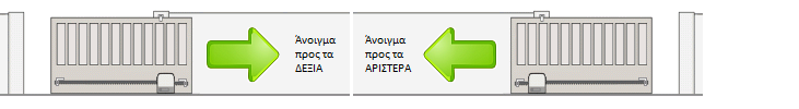
The base of the FCM 400 motor must be placed at a specific point for the entire installation to function correctly. Below is a detailed description of where the base should be placed depending on whether the door opens to the right or to the left. (left and right are defined as looking at the door from the side where the mechanism and rack are installed)


To find the correct base position, follow these steps:
- Push the door leaf, by hand, to the fully closed position. Place the mechanism base on the ground, at a distance of at least B from the edge of the door leaf.
- Push the door leaf, by hand, to the open position. The base must be at a distance C from the edge of the door. If this condition is met, proceed with the installation. If this condition is not met, there are 2 options:
- Accept that the door leaf will not open fully (but will open to the point where it reaches a distance C from the base). Choose this solution if the clear opening is sufficient and what remains continues to meet your needs. (there is a risk that a vehicle may collide with the door leaf if the opening is not sufficient due to carelessness)
- Extend the door in length, by extending the door leaf. It can be extended in length across its entire height or only at the point where it comes into contact with the rack.
NORTON FCM 400 motor - Base - Installation height
For the sliding motor to function correctly, it must be installed at the correct height to work perfectly with the rack. Depending on the door's design, it is often not possible to install the rack at the desired height. So we must check that at the point where we want to install the motor and therefore the rack, proper support is possible. Below are detailed diagrams and distances for the correct installation of the mechanism's base in relation to the rack.


H1= 18mm (motor support base height)
H2=72mm (base top to gear top)
H3=15mm (gear top to rack spacer axis)
H1+H2+H3=H1+H4+H5=105mm (base bottom to rack spacer axis)
H4=67mm (base top to rack bottom)
H5=20mm (rack bottom to rack spacer axis)
H6=10mm (spacer axis to rack top)
H1+H4=85mm (base bottom to rack bottom)
Ho= height of elevated foundation (the base can be placed at an elevated point for spatial reasons. In this case, the motor is protected, e.g., in case of flooding).
Considering the above dimensions, we perform a pre-check of the existing installation:
- If there is no rack, we check if the point where the rack is to be installed can be properly supported. Otherwise, we will have to change the motor's base height or reinforce the door to properly support the rack.
- If there is a rack, we must check that it can work with the motor at its current location. Otherwise, we will have to change the motor's base installation height or uninstall and reinstall the rack in a new position.
Sliding motor rack - Features

The movement from the motor to the door is transmitted via the rack. Racks are usually metal, have a diametrical pitch of 4 (module 4), and a cross-section of 12x30mm. Each piece is 1 meter long and comes with 3 spacers. They are galvanized for greater durability over time and can work with doors up to a maximum weight of 2 tons. Depending on your needs, you can add the corresponding meters of rack to your set. If the options we offer are not sufficient for your door, please contact us to order the correct quantities or add them to your order from the link below:
NORTON FCM 400 sliding motor metal gear

The metal gear transmits movement from the motor to the garage door. It has a protective cover to prevent accidents.
NORTON FCM 400 sliding automation kit - Wiring

For the wiring of the Norton FCM 400 sliding motor, the following are required:
- A 3X1.5mm² cable suitable for outdoor use for the motor. In case of a long distance to the motor's location, it is preferable for the cross-section to be 3X2.5mm². We recommend a separate fuse in the control panel for the motor so that its operation is not affected by other devices (lights, etc.).
- For wired photocells (can be added to the kit), a 4×0.6mm² cable is required for the receiver and a 2×0.6mm² cable for the transmitter. If it is not possible to run a cable to the opposite side for the transmitter, then photocells with a reflector can be installed, which require only a 4×0.6mm² cable to the transceiver (on the side where the motor is also located).
- For the pushbutton or key switch (not included in the kit), a 2×0.6mm² cable is required.
- For a warning light (not included in the kit), a 1×1.0 mm² or 2×1.0 mm² cable is required.
Special care must be taken to protect the cables from moisture. (preferably inside conduits)
Norton FCM 400 motor control panel

The Autotech S5060T control unit accompanies the Norton FCM 400 motor in all versions that include remote controls. The Autotech S5060T panel is tested, works perfectly with the Norton FCM 400 motor, and has many capabilities.
Key features:
- We can adjust the motor's force.
- It has a connection for the motor's limit switches.
- It has a slow start and slow stop option that contributes to the installation's longevity.
- It has an automatic closing option. The user selects how long the door will close after opening.
- It can accept safety photocells that interrupt the door's closing when an obstacle is detected and give a command for reverse movement (door opening).
- Electric braking option.
- There is an option for the opening direction.
- It has a connection for a pushbutton (simple or with a key). The pushbutton's functions can be: open-stop-close-stop-open... or just open in combination with automatic closing.
- It has a connection for a 230VAC lighting lamp or a 230VAC warning light without a flasher.
- It has a built-in remote control receiver.
- Sufficient information with LED indicators.
In general, it is a control unit that has stood out in its category. Especially the slow stop and the ability to adjust the motor's force give it an advantage over the competition.
ProfelmNet PSD-36T Remote Controls
The selection for the Norton FCM 400 kit is from 1 to 5 remote controls. However, you can add more by phone or via the link below:
Add ProfelmNet PSD-36T remote controls at 433.92 MHz
The ProfelmNet PSD-36T remote controls at 433.92 MHz are practical, easy to use, and have a modern design.
They can store up to 4 doors and have the ability to copy remote controls of the same type, as well as older fixed-code remotes that operate at 433.92 MHz.
Safety photocells - Operation
Safety photocells are an economical but essential accessory for every type of garage door. They prevent accidents and require no maintenance or special attention from the user.

Safety photocells consist of a transmitter and a receiver. The transmitter emits an infrared light beam, in the invisible spectrum, which is directed towards the receiver. When there is no obstacle to interrupt the beam, the door operates normally. When the beam is interrupted by an obstacle (vehicle, pedestrian, pet, etc.) during the door's closing, the control panel instructs the mechanism to stop closing the door and start reversing (opening). If the beam is interrupted while the door is opening, it continues its path normally, while if it is open, it is not allowed to start closing.
If it is not possible to run cables for wired photocells, we can choose the solution of photocells with a reflector. These photocells require wiring only on one side of the door (the motor side), making them easier to install. They are preferred in cases where the door and surrounding area have been completed without provision for wiring. They have a small extra cost compared to wired photocells but are a very good solution when wiring cannot be run. In the set, you can add either wired photocells or photocells with a reflector.
Wired photocells NOLOGO IR5001P / Zoom-Z2E
The NOLOGO IR5001P / Zoom-Z2E photocells are a reliable choice of wired photocells consisting of a transmitter and a receiver, with a range of 20m. As wired photocells, they require wiring on both sides of the opening.
Technical specifications of NOLOGO IR5001P / Zoom-Z2E photocells:
- Operating voltage: 12 or 24 V DC, 12 or 24 V AC
- Maximum operating distance: 20m
- Maximum switch contact current: 0.5 A at 48 V AC/DC
- Transmitter operating current: 25 mA
- Receiver operating current: 35 mA
- Interference rejection circuit from other light sources
- Auto focus
They are usually placed 50cm above the ground. They are simple to install and can prevent major damage and accidents. Their operation is trouble-free as they require no maintenance, are not affected by weather conditions, and do not require any action from the user during their use.

Safety photocells with reflector Witt Sensoric RP25
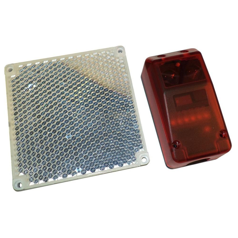
The biggest advantage of photocells with a reflector is that they only require wiring on one side, where the transponder is placed. The reflector is placed opposite. The reflector has dimensions of 10x10cm, while the dimensions of the transponder are:
Characteristics of safety photocells with reflector Witt Sensoric RP25:
- Convenient size and shape for both the transponder and the reflector.
- Do not require batteries like other competing wireless photocells.
- Reliable operation even in bad weather conditions. (suitable for outdoor use)
- 15m range covering the majority of sliding gates.
- They are not interfered with by sunlight or other light sources as they operate with a polarized light filter. This means they can detect even reflective objects between the transponder and the reflector, so they are not easily fooled by the polished surface of a car.
Technical characteristics of wireless photocells Witt Sensoric RP25:
- CE marked
- Comply with EMC directive 89/336/EEC, EN 61000-6-2 and EN 61000-6-4 standards
- Operating voltage: 10-40 V DC or 24 V AC (±25%)
- Minimum operating distance: 0.5m
- Maximum operating distance: 15m
- Polarized light beam arrangement: excellent resistance to interference
- Degree of protection against dust and moisture: IP-67
- Easy cable installation. Features removable terminal block - cable gland and elastic washer for waterproofing
- Protection against wrong polarity power supply
- Beam direction is easily adjusted with 3 screws.
- Features red-green LED for obstacle detection or operation (Red when there is an obstacle - Green when there is no obstacle)
- Immediate operation in less than 200 ms from the moment it is connected to power
- Maximum transponder consumption: 30 mA at 24 V DC
- Maximum contact current: 0.3 A at 100 V AC, 0.5 A at 48 V DC
- Dimensions: 86x44x39 mm
- Beam width: approximately 1.5° total
- Response time: less than 10 ms from the moment the beam is interrupted
- Reset time: the contact returns to its normal state in less than 100 ms from the moment the beam interruption ceases
- Operating temperature: -25 to +60 °C
- Test input. When contact #1 is connected to 0 V (GND), the transmitter turns off.
Packaging of the NORTON FCM 400 sliding gate kit
If the kit includes a metal rack, your order will be delivered in 2 packages. One will contain the motor and accessories, and the other will contain the metal rack (due to weight and length).
The kit is delivered pre-programmed and ready for installation.
NORTON FCM 400 Kit Installation Instructions
Our instructions are the culmination of thousands of sliding motor installations. Consequently, they are simple, easy to follow even by those not familiar with automation. If the wiring has been installed, one only needs to be handy and have basic knowledge of welding.
The remote controls are delivered set up and ready for operation. However, it is good to save the instructions in case new remote controls are added in the future or any other need arises.