

VDS SL1000-OIL Sliding Gate Opener (Standard Kit) S
- For a maximum leaf weight of 1000kg
- Non-reversible, in oil bath
- Up to 48 open/close cycles per hour. (at 20°C)
- Up to 150 open/close cycles per day. (for a 5m gate)
- Single-phase motor (230 VAC)
- Mechanism dimensions: 310x150x264 mm (LxWxH)
- Gate leaf travel speed: 10 m/min
- Motor absorbed power: 330 W
- Motor thermal protection: 140 °C
- Features a key-operated release cover (manual operation)
- Protection rating: IP44
- Gear type is Z16/module 4
- Steel rack m4
- Motor country of origin: Italy
- Warranty: 2 years
To order this product, please call us at 210.555.0632 or buy it online from our e-shop.
The VDS SL1000-OIL (kit-Standard) S set includes:

- VDS SL1000-OIL sliding gate operator for 1000kg gate with all its accessories:
- Operator mounting base with screws and anchors
- Manual release keys (2 pcs)
- Limit switch activation plates
- Detailed instructions written in Greek
- ProfelmNet PSD-36T remote control at 433.92 MHz, 2 pcs
- Steel rack, 4m
- Wired photocells, 1 set
The VDS SL1000-OIL (kit-Standard) S set is a complete kit for gate installation with all necessary accessories. Other materials can be added to it depending on your needs.
Criteria for installing the VDS SL1000-OIL operator on your gate
- It can be installed on a gate leaf with a maximum weight of 1000kg.
- It can be used up to 48 times per hour.
- It can be used up to 150 times per day.
A gate weight of 1000kg is a fairly high limit, assuming that the average weight of sliding gates is usually 60-70kg/m. However, if the gate's weight is unknown, it's best to consult the manufacturer. From our experience, the above operator covers most sliding gate applications.
The 48 uses per hour cover most apartment building situations, as the gate can operate almost every minute during peak hours. The motor has thermal protection. This means that if usage is exceeded and it overheats, movement stops until the normal temperature is restored. It is logical that shorter gates, in a cold environment, can perform more cycles than longer gates in a warm environment. If the motor stops due to overheating, the gate must be operated manually.
The daily uses can cover more than 35 cars, each using it 4 times per day. These uses (compared to the hourly uses) represent optimal operation for the mechanism to last many years without problems.
Characteristics and advantages of the VDS SL1000-OIL operator

- The VDS SL1000-OIL operator is built for intensive use. It can be used in apartment buildings or commercial premises with heavy traffic.
- Suitable for heavy sliding gates.
- Silent operation.
- Minimal maintenance requirements.
- Low price for an oil bath operator.
- Easy installation.
- Convenient dimensions:

The windings and mechanical parts of the VDS SL1000-OIL operator are immersed in an oil bath. This provides two significant advantages: better lubrication and better cooling.
Better lubrication is achieved as the entire mechanical part of the mechanism "swims" in the special oil.
Better motor cooling is achieved as the oil ensures there is no area that is exceptionally hot compared to the others, since the oil "bathes" the entire interior of the motor, reducing both the risk of overheating and corresponding wear. It also absorbs the heat generated both by the mechanical operation of the motor and, primarily, by the electrical operation of the motor (the heat generated in the motor windings, which also "swim" in the oil) and transfers it evenly to the motor walls, which dissipate it into the environment, achieving extremely effective cooling.
The motor has a special screw that is tightened upon delivery to prevent oil leakage. This screw is located under the motor cover. After installing the motor, this screw must be loosened by 2 turns so that the oil reservoir (the sump) can "breathe." This is the oil breather screw.
For checking the oil level, the motor has an external indicator for easy inspection. This is a great advantage of the VDS SL1000-OIL motor, as the cover does not need to be removed for inspection.

Sliding gate with operator - Features

A classic sliding gate arrangement with an operator naturally includes the gate leaf, which has wheels at its bottom. The wheels must be well-maintained to avoid impeding the gate's and operator's movement.
On the ground, the rail on which the wheels move is correctly secured. The rail must be straight, without bumps or deformations.
The gate leaf is held upright by the rollers. The rollers are positioned so that they are always in contact with the gate from the fully open to the fully closed position. They must be stable and not allow the gate to deviate from its path, but without hindering its movement. They are placed at the top of the gate and in the middle of its travel.
The last accessories (for a gate without an operator) are the mechanical gate stops. The stops define the gate's travel, i.e., the final position of the gate for both opening and closing.
To automate a gate leaf, we install a metal (or plastic) rack. The rack is a toothed bar that cooperates with the motor's gear to transmit motion.
The motor is placed in the center of the gate's travel so that it always maintains contact with the gate. It features a gear that transmits motion from the mechanism to the gate via the rack.
Beyond the mechanism, essential accessories for the safety of the entire installation are the safety photocells. The safety photocells are placed on either side of the opening and check for obstacles in the gate's path. If an obstacle is detected during the gate's closing, the photocells send a command to the mechanism's control panel, and the gate's closing stops.
For even greater safety, a safety beacon could also be installed, which provides a visual signal when the gate is in operation. This is usually installed when the gate is adjacent to busy roads, roads with heavy traffic, and in areas where visibility is limited.
Finally, in cases where the range of the remote controls is not desirable, an external antenna can be installed to boost the signal.
VDS SL1000-OIL sliding automation base
The mechanism comes with a base specifically designed for proper and sturdy support. The foundation should ideally be concrete to ensure that the mechanism is properly supported.
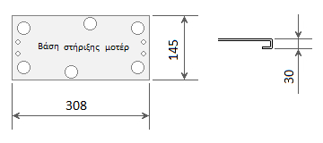
For the installation of the sliding mechanism's base, we check the foundation and wiring. (the best solution is a reinforced concrete foundation with a conduit for the wiring)
Position of the VDS SL1000-OIL sliding automation base
The base of the sliding gate operator must be placed at a specific point for the motor to function correctly. Below, the precise point where the base should be placed is defined, depending on whether the gate opens to the right or to the left. (left and right are defined as looking at the gate from the side where the motor and rack are installed)


To find the correct position for the base, follow this procedure:
- Push the gate leaf, by hand, to its fully closed position. Place the mechanism's base on the ground, at a distance of at least B from the edge of the gate leaf.
- Push the gate leaf, by hand, to the open position. The base must be at a distance C from the edge of the gate. If this is true, proceed with the installation. If this condition is not met, there are 2 options:
- Compromise by accepting that the gate leaf will not open completely (but will open to the point where it reaches a distance C from the base). This solution is chosen if the clear opening is sufficient and what remains continues to meet our needs.
- Increase the length of the gate by extending the gate leaf. It can be extended lengthwise across its entire height or only at the point where it comes into contact with the rack.
Mechanism Installation (height) - Detailed dimensions
The installation height of the mechanism is extremely important for the overall installation process. What matters is the height in relation to the rack for their proper cooperation. Often, the gate's design determines where the rack will be placed so that there are attachment points for the rack on the gate. Below are detailed drawings for the installation height of the mechanism in the case where the rack has been installed with its teeth facing downwards. (this is the recommended and most common solution)


H1= 30mm (motor mounting base height)
H2=90mm (top of base to top of gear)
H3=15mm (top of gear to rack spacer axis)
H1+H2+H3=H1+H4+H5=135mm (bottom of base to rack spacer axis)
H4=85mm (top side of base to bottom of rack)
H5=20mm (bottom of rack to rack spacer axis)
H6=10mm (spacer axis to top of rack)
H1+H4=115mm (bottom of base to bottom of rack)
Ho= height of raised foundation (the base can be placed on a raised spot for spatial reasons. In this case, the motor is protected, e.g., in case of flooding).
Based on the above dimensions, a pre-check is performed before installing the mechanism. There are two cases:
- If a rack already exists, we check if the height at which it has already been placed is suitable in relation to the dimensions of the mechanism and the height at which its gear is positioned. If the dimensions do not match, we either need to raise the mechanism's base (if the rack is high) or change the rack's position. (uninstall and reinstall)
- If there is no existing rack, we check if there are available mounting points on the gate at the desired installation height of the rack. Otherwise, we will have to place the entire structure higher by modifying the foundation where the mechanism's base will be installed.
A key point of attention is the clearance that must exist between the gear and the rack. Ideally, this clearance should be 1.5mm.

If this clearance does not exist, the mechanism is forced to carry the gate along its entire travel instead of simply pushing the gate. This will cause wear and tear and sooner or later problems will arise in its operation.
Conversely, if the clearance is large, the cooperation between the gear and the rack will not be correct, and vibrations and stress will be created on the motor. Therefore, special attention is required to create this clearance.
Metal rack
The metal rack is delivered in one-meter sections. It is galvanized for greater resistance to external conditions. The cross-section of the rack is 12x30mm, the diametral pitch is 4 (module 4), and it has 3 spacers per piece. It can be installed on gate leaves with a maximum weight of 2 tons.

Autotech S5060T control panel for sliding gate operators

The Autotech S5060T control panel is included in the set and is integrated into the mechanism. It is a control panel that combines ease of use with all necessary functions and has been time-tested. It combines perfectly with the VDS SL1000-OIL mechanism.
Technical specifications:
- It has a socket for the mechanism's limit switches.
- We can adjust the mechanism's force.
- There is the possibility for soft start and stop for less wear and tear on the mechanism and the garage door.
- It accepts safety photocells that interrupt movement when an obstacle is encountered during gate closing and initiate reverse movement (opening).
- There is an available setting for automatic gate closing with user-selectable closing start time. Photocell use is essential for automatic closing function.
- There is an option for electric braking.
- The opening direction is adjusted by a microswitch.
- The panel can accept a push button (key switch or simple push button).
- The panel can accept a 230VAC warning light without a flasher or a 230VAC lighting lamp.
- It features an integrated receiver with simple operation.
- User information regarding the mechanism's functions is provided by LED lights.
The above control panel has been tested by thousands of users and has proven to be extremely reliable. Furthermore, it features functions such as mechanism force adjustment, slow start, and stop, which make it one of the best choices currently on the market.
ProfelmNet PSD-36T remote controls at 433.92 MHz.
The ProfelmNet PSD-36T remote controls feature an excellent design while being user-friendly and simple, both in their use and programming. They have been tested by thousands of users and do not present problems. They can receive up to four commands from different mechanisms, which makes them convenient for users who have more than one automation in their daily use.

Sliding mechanism installation procedure - Summary
Briefly, the steps for installing a sliding garage door operator are as follows:
- Check that the door operates smoothly manually.
- Check the wiring if it exists or install it.
- After the checks, the motor's base is installed. This requires a stable foundation. Usually, a reinforced concrete base is the appropriate solution.
- Mount the motor on the base.
- Install the rack.
- Installation of accessories (if any)
- Checking the proper functioning of the construction and explaining all details for safe use to the users.
The above are just a brief outline of the steps for installing a sliding mechanism. Inside the mechanism's packaging, you will find detailed, step-by-step instructions, well-written and easy to follow.
Manual override of the VDS SL1000-OIL sliding mechanism
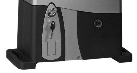
The manual override procedure for the VDS SL1000-OIL mechanism is a simple and easy process for all users. With the key, open the release door and push it to the fully open position. The garage door now operates manually. By reversing the process (closing and locking the door), we re-engage the mechanism.
Packaging of the VDS SL1000 OIL mechanism kit (kit-Standard) S
The VDS Simply SL1000 (kit-Standard) S kit is delivered in two packages. One contains the mechanism, the remote control, the photocells, and any accessories that may have been ordered extra from the kit.
The second package contains only the metal rack due to its weight and length.
The kit is delivered ready for installation as it has been checked by our technicians and the remote control is programmed.
Installation instructions for the sliding garage door kit
The kit comes with detailed instructions in Greek. They have been edited by us to be easy to follow even by people who are not directly involved with the subject.
They contain detailed steps for each stage of the installation, from the motor base and the rack to accessories such as photocells and push buttons. Detailed instructions for the Autotech S-5060T control panel, which is integrated into the mechanism, are also included.