RIB K500 Sliding Gate Motor (Kit-Economy S)
- For a maximum gate leaf weight of 500 kg
- Non-reversible, permanently lubricated mechanism
- Maximum number of consecutive open/close cycles, at 20°C: up to 25
- Up to 300 open/close cycles per day.
- Single-phase motor (230 VAC)
- Mechanism dimensions: 274x245x267 mm (LxWxH)
- Gate leaf movement speed: 9.6 m/min
- Motor power consumption: 229 W
- Features a key for disengagement (manual operation)
- Protection degree: IP54
- Gear type is Z12/module 4
- Metal rack module 4
- Country of origin: Italy
- Warranty: 2 years
To order this product, please call us at 210.555.0632 or buy it online from our eshop.
Contents of the RIB K500 set (Kit-Economy S)

The RIB K500 set (Kit-Economy S) for sliding garage doors includes:
- RIB K500 sliding mechanism for gates up to 500Kg.
- Autotech S5060T control panel
- Metal rack module-4, 3m
- ProfelmNet PSD-36T remote control at 433.92 MHz, 1 pc
- Motor mounting base (includes mounting screws and anchors)
- Limit switch activation brackets
- Manual release keys, 2 pcs
- Detailed installation instructions in Greek
The RIB K500 (Kit-Economy S) set is a basic solution for automating a sliding gate with a length of up to 3m. Depending on your needs, additional products can be added to fully meet your requirements.
Criteria for selecting a sliding motor
The key characteristics of the RIB K500 motor that should be considered for its selection are the following:
- Suitable for gates weighing up to 500kg
- Maximum number of consecutive open/close cycles, at 20°C: up to 25
- Maximum daily usage: 300 open/close cycles
500kg is a weight limit that covers most domestic gate cases. The essential feature a gate must have is smooth movement in manual operation. For the gate to be automated, it must not present difficulty during movement. Even a 100kg gate with movement difficulty will cause the motor to malfunction. Conversely, a perfectly maintained 500kg gate will operate smoothly and without problems.
The great advantage of the RIB K500 motor is its ability to operate intensively:
- The 25 consecutive open/close cycles ensure that even during peak hours, the gate can operate, practically continuously, without issue.
- 300 uses/day are sufficient even for residential complexes or commercial premises. Unlike the competition, the RIB K500 can be used without fear of overheating and going out of service, even under conditions of intensive use.
Essential checks before installing the RIB K500 sliding mechanism
The gate must function perfectly as a manual gate. If it presents any problem as a manual gate, converting it to an automatic one will not only fail to solve it but will worsen it, with the risk of damage to the automation.
No automation installation should be carried out on a gate that does not already work perfectly as a manual gate.
The minimum checks we perform to assess how well the gate operates are:
1. The track on the ground must be perfectly horizontal and straight. We check that it has no distortions, dents or bumps, that it is well supported on the ground, and that it does not sink at any point when the gate's wheels roll over it.
2. The gate wheels must be in good condition, suitable for the gate's weight, and have a profile compatible with the track's profile (e.g., no wheels with a circular profile on an angular profile track).
3. The surface of the gate leaf must be completely flat (no "bellies").
4. The gate leaf must move smoothly, throughout its entire travel (both opening and closing), without its resistance to movement changing. We clean the track of any debris (e.g., pebbles, dirt, leaves). We move the gate by hand from end to end, at a slow, steady speed. The speed should be approximately that of the mechanism. If at some points the gate leaf's resistance suddenly increases, we stop and look for the reason. Possible causes are:
- A piece of welding protrudes at one of the track's joints.
- There was some debris we didn't clean.
- One of the gate's wheels jams.
- The gate leaf jams in the support rollers.
5. The gate leaf must move without jerking and swaying back and forth. The support rollers must interact well with the gate leaf. They must embrace it firmly and without a large gap, so that it cannot "play" back and forth. Also, they must keep it completely vertical. This must be true throughout the gate leaf's travel. If such problems appear at some points, we stop and look for the reason. Possible causes are:
- The surface of the gate leaf on which the support rollers rest is not smooth and flat.
- The support rollers do not rotate smoothly, are not firmly supported, or are excessively worn.
6. We particularly check how much the gate leaf moves back and forth when the gate is almost closed (as much as the gate leaf is very close but has not yet "landed" on the opposite side), especially if the gate leaf has a long length and height. We pay particular attention if the movement is such that it can cause the gate leaf to collide with the edges of the receiver ("pocket" - closed position limit stop) that the opening may have on the side where the gate closes. For this reason, we swing the gate leaf by hand. If the gate leaf moves excessively back and forth, we stop and look for the reason. Possible causes are:
- The support rollers do not interact well with the gate leaf, so it can "play" excessively.
- The gate leaf is not rigid enough and easily distorts.
- The point where the support rollers are mounted, and thus the gate leaf (e.g., a metal column), is not rigid enough and easily distorts.
7. The gate leaf must move without up and down jolts and shaking. If such problems appear at some points, we stop and look for the reason. Possible causes are:
- There was some debris we didn't clean.
- There is a gap in one of the track's joints.
- One of the gate's wheels does not have a completely circular circumference or is excessively worn.
- The track sags instead of being completely horizontal everywhere.
8. When the gate is closed, the gate leaf must secure into the receiver of the opposite position ("pocket" or closed position limit stop, if such a receiver exists) leaving at least 2 centimeters of free space. In this position, it is advisable for the gate leaf to be secured in a way that does not allow it to be lifted with a crowbar (a common method of forced entry for small automatic gates).
9. The gate must have mechanical stops in the open and closed positions of the gate leaf.
We check the rolling quality by moving the gate manually at a low, constant speed, not greater than that of the mechanism (i.e., not more than 10 to 12 meters per minute). We perform the check both when opening and closing.
Basic installation features of the RIB K500 sliding mechanism

The above image shows a typical installation of a sliding automation system. A basic prerequisite is the existence of a correctly and functionally sound gate. The gate must be 30-40cm longer than the opening. This allows the motor to be placed outside the opening and the entire width of the gate to remain free for vehicle passage.
The track, on which the gate's wheels roll, is installed on the ground. The track is twice the length of the gate to cover its entire travel. The rollers hold the gate in a vertical position. The stops define the open and closed positions of the gate. All of the above are essential for the smooth operation of the gate and must exist prior to the mechanism. Also, a basic prerequisite is that the gate operates smoothly, with minimal effort, and has been installed without inclination.
The motor has a gear through which movement is transmitted to the gate. The metal rack (welded) is placed on the gate and moves with it. The gear rotates within the rack's teeth, and the gate moves.
An essential accessory for sliding gates are safety photocells. Safety photocells monitor the gate's path to ensure there are no obstacles and prevent accidents. Classic photocells consist of a transmitter and receiver and require wiring on both sides of the gate. If this is not possible, safety photocells with a reflector can be installed.
Also, if the gate is next to a busy road or visibility is poor, the warning beacon alerts passing vehicles to the vehicle exiting the gate.
Installation procedure for the RIB K500 sliding mechanism
When the mechanism is installed on the base and combined with the standard metal rack, the basic heights are those shown in the diagram below.

Because the holes for the spacers are oval, these dimensions can be increased or decreased by approximately 5 mm in total.
If, at the height where the center of the spacers is marked, our gate does not have a structural element stable enough to weld the rack, then we must:
- either install the entire mechanism higher.
- or add such an element to the gate (e.g., a horizontal hollow section or a thick plate).
1. We choose the position of the motor base, so that it is within the limits indicated by the above diagrams.
Note 1: The base must be supported either on an existing reinforced concrete floor, at least 10 cm thick, or on a foundation specifically constructed for this purpose (with a length and width at least as large as the base and a depth of at least 20 cm).
Note 2: At this point, water should not accumulate or pass through. If this occurs, we should install the mechanism in an elevated position.
Note 3: For the gate to leave the entire width of the opening free when opening, the gate leaf must be at least 420 mm longer than the width of the opening. If this is not the case then:
- either we extend the gate leaf (or, at least, add an extension to support the rack on the side where the gate opens)
- or we leave the gate leaf as is and accept the reduced clear passage width.
2. We prepare the base for installation
3. We select the positions of the peripheral devices (photocells, beacon, push-button, etc.).
4. We install the power cables and the cables for the peripheral devices
Note 1: The motor must be connected to the electrical network by a qualified electrician.
Note 2: All cables must be placed inside suitable protective conduits.
We check with a spirit level that the base is horizontal, both in the direction parallel to the gate and, especially, in the direction perpendicular to the gate. The base must be perfectly parallel to the gate.
If there are cables coming out of the ground under the mechanism (e.g., power supply, safety photocell connections, etc.), we pass them through the large hole at the top of the base.
The method of supporting the base depends on the type of flooring. We can use screws with metal anchors, if there is already a durable floor, or create a reinforced concrete foundation in which we will anchor the base.


5. We support the base on the ground in such a way that it is perfectly horizontal and parallel to the gate. The base must be very well supported on the ground.
6. We remove the mechanism cover. To do this, we unscrew the corresponding screws and pull the cover upwards.
7. We remove (unclip) the terminals from the control panel before performing any welding.
8. The mechanism is secured to the mounting base 2 onto the protruding screws. We place the mechanism on the base and screw it to it.


9. Disengage the mechanism:
Open the door, insert the key into the lock, and turn it counter-clockwise as many turns as necessary until the key stops.
In this position, the mechanism has been disengaged, meaning its gear can be manually rotated. The mechanism will remain in this state (disengaged) until you complete the rack installation.
If you are installing the standard metal rack, then note the following:
The rack consists of 1 m pieces.


Each piece has 3 oval holes. In each hole, we screw in a spacer, as shown in the diagram.
Initially, we screw each spacer approximately in the center of the oval hole (so that we can later, if necessary, make an adjustment up or down). We screw the spacers tightly enough so that they don't wiggle. The final tightening will be done after the rack is installed and checked.
We will weld the wide part (flange) of the spacer onto the gate.
When installing a sliding gate mechanism, we ensure that the rack does not rest on the gear but is slightly above it, creating a small gap.

If we do not create the correct gap, or even worse, if the gate rests on the gear, we will not have proper cooperation between the rack and the gear, and sooner or later, we will face problems in the operation of the mechanism and/or the gate (creaks, noises, gear breakage, mechanism uprooting, etc., etc.).
The recommended gap is 1.5 mm
Never lubricate the rack or the gear. Doing so does not contribute to the proper functioning of the automation. On the contrary, if we do, the grease or oil will collect dust, sand, dirt, and debris, creating a mixture that wears down the automation.
When moving from one rack section to the next, the pitch of the rack must be maintained, and not simply have one section touching the other. To ensure this, we must use a third piece of rack and two clamps as a guide.
The rack sections must not, under any circumstances, be welded to each other, nor welded to the spacers.

10. Fully open the gate and place the first rack section. Ensure that there is a necessary gap of 1.5 mm between the rack and the pinion. Continue with the remaining rack sections, making sure the gap is uniform and that the pitch is maintained from section to section.
Note: The rack must engage with the pinion along its entire length, across its full width (and at the center of its width, if possible). If necessary, the mechanism's distance from the gate leaf can be adjusted: Loosen the screws connecting the mechanism to the mounting base and move it vertically in relation to the gate leaf.
11. Once the rack is installed, check its correct positioning by manually opening and closing the gate at a steady low speed. The movement must be smooth everywhere, without changes in resistance and without the motor shaking. If you observe any problem, slightly loosen the screws on the spacers of the corresponding rack section (so it can move slightly up and down) and re-adjust it.
12. After confirming the correct positioning of the rack, tighten the screws on the spacers.
13. Next, proceed to adjust and connect the electronic control panel, safety photocells, and other peripheral devices, according to their respective instructions.
ATTENTION: After connecting the mechanism to the power supply, do not operate it automatically until you confirm the correct opening direction and install the limit switches.
Until then, keep the mechanism disengaged (in manual mode).
The limit switches are the two plates with inclined sides and are installed on the rack, as shown in the adjacent figure.
Do not use makeshift limit switches, nor bend or modify the mechanism's limit switches. Improper cooperation between the limit switches and the limit switches causes problems in the automation's operation.
Do not weld the limit switches to the rack as this eliminates the possibility of adjustments.

14. Install the limit switches at both ends of the rack to activate the motor's limit switches. The open and closed position limit switches are activated as the spring-loaded stem protruding above the pinion is moved by the limit switches, in one direction or the other.
Note 1: The limit switches must be adjusted so that the gate stops at least 2 cm before hitting the mechanical stops in both the open and closed positions of the gate leaf. The gate must not hit anywhere when it reaches the fully closed or fully open position.
Note 2: The recommended way to find the correct position of the limit switches is to observe when the control panel detects that each of the two limit switches is activated (via the corresponding indicator LEDs). This obviously requires the mechanism to be connected to the power supply. The procedure is as follows:
• Make sure that the control panel wiring is correct in relation to the opening direction of the mechanism (whether it opens to the right or to the left). The wiring must be correct before proceeding with adjustments.
• Manually move the gate towards the open position and observe when the indicator LED of the open position limit switch turns off. Correct the position of the limit switch so that there is a safety distance of at least 2 cm from the mechanical stop of the open position.
• Manually move the gate towards the closed position and observe when the indicator LED of the closed position limit switch turns off. Correct the position of the limit switch so that there is a safety distance of at least 2 cm from the mechanical stop of the closed position (or the pillar).
15. When the limit switch adjustments are complete, we confirm the overall proper functioning of the automation. For this purpose, we engage the mechanism and, using a remote control or push button, open and close the gate several times. We especially check the correct operation of the limit switches (the points where the gate stops), the safety photocells (they prevent closing if their beam is interrupted), and the gate's stopping function when it encounters an obstacle. If necessary, we make new adjustments. This check should be repeated at least once every six months.
16. Inform all users about the mechanism's operation, its proper use, and any potential risks that may still exist during its operation.
Sliding gate motor pinion RIB K500
The motor has a pinion for transmitting motion to the gate. The pinion has protective covers to prevent accidents.

Also, after the installation is complete, the screw must be removed as indicated in the above photo.
Wiring of the RIB K500 (Kit-Economy S) sliding gate kit

For the wiring of the RIB K500 (Kit-Economy S) sliding gate kit, the following are required:
- For the mechanism, a 3x1.5mm² cable suitable for outdoor use. If the distance to which the motor will be installed is long, it is preferable for the cross-section to be 3x2.5mm². It is also good for it to be on a separate fuse in the control panel so that its operation is not affected by other devices (lights, etc.).
- For classic photocells (not included in the kit), a 4x0.6mm² cable is required for the receiver and a 2x0.6mm² cable for the transmitter. If it is not possible to run a cable for the transmitter, then photocells with a reflector can be installed, which only require a 4x0.6mm² cable to the transceiver (on the side where the motor is also located).
- For the push-button or key-button (not included in the kit), a 2x0.6mm² cable is required.
- For a warning light (not included in the kit), a 1x1.0 mm² or 2x1.0 mm² cable is required.
- Cables must be in conduit and protected from moisture.
Control panel of the RIB K500 (Kit-Economy S) set
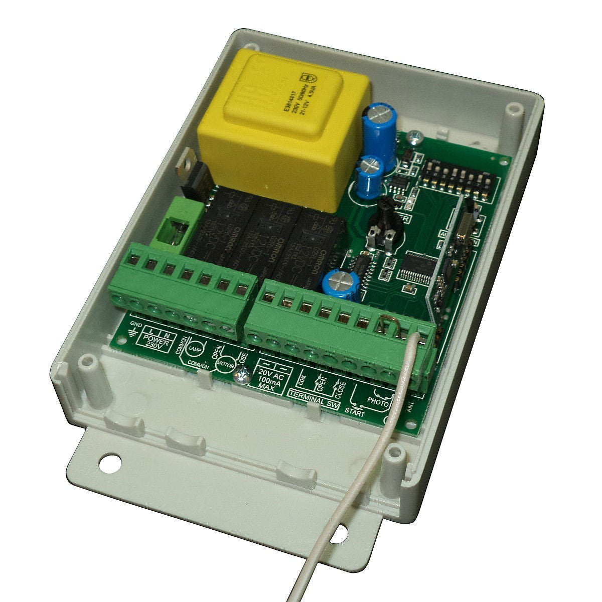
The RIB K500 (Kit-Economy S) kit includes the Autotech S5060T control panel which is integrated into the motor. It is a tested control panel that has proven to be reliable and functional. It works perfectly with the RIB K500 motor, is easy to use, and simple to set up.
Features:
- Available socket for motor limit switches
- Motor force adjustable
- Soft-start and soft-stop options for smoother garage door operation.
- Accepts safety photocells. It stops the gate's movement if there is an obstacle in its path and commands it to return to the open position.
- Can accept automatic closing. The user chooses how long they want the gate to close automatically. (This option is not recommended without the installation of photocells)
- Features an electric braking option
- Features a microswitch that adjusts the opening direction.
- Accepts a push-button (simple or with a key). The push-button can have 2 functions: Open-stop-close-stop-open... or open only, which can be combined with automatic closing.
- Accepts a 230VAC lighting lamp or a 230VAC warning light without a flasher.
- The receiver is integrated, with easy operation.
- Features LED indicators that provide information about the motor's functions.
This control panel was chosen over the competition due to its reliability and numerous functions. Especially the soft-stop functions and the ability to adjust the motor's power distinguish it from other sliding gate automation control panels.
Remote control for RIB K500 (Kit-Economy S) sliding gate kit
The RIB K500 (Kit-Economy S) sliding gate automation kit comes with a ProfelmNet PSD-36T remote control at 433.92 MHz. The ProfelmNet PSD-36T remote control is easy to use, practical, and functional. It can store up to 4 gates. It uses a fixed 12-bit code at 433.92 MHz. It can copy remote controls of the same type and older fixed-code remotes that operate at 433.92 MHz.

Packaging of the RIB K500 (Kit-Economy S) sliding gate kit
The RIB K500 (Kit-Economy S) kit is delivered in 2 separate packages. One contains only the metal rack and the other contains the motor with its accessories.
Before shipment, the kit is inspected by our technicians. It is also delivered pre-adjusted and ready for installation.
Installation instructions for the RIB K500 (Kit-Economy S) kit
The RIB K500 (Kit-Economy S) kit comes with complete, detailed, and easy-to-follow instructions. They are in Greek, written by our company's personnel with extensive experience in automation.
Even someone without experience in automation but who is "handy" can follow them and successfully complete the process. The only difficulty lies in installing the rack and specifically in welding.
If the cables have been laid, the connection is a simple matter. The remote controls are delivered pre-set, although instructions are included in case they are needed in the future.
Detailed instructions are included for: motor installation, rack installation, and connections (power and peripherals).