

Motorline BRAVO 500 Sliding Gate Operator Kit (Kit-Basic)
- For maximum door weight: 500 kg
- Non-reversible permanent lubrication mechanism
- Up to 14 open/close cycles per hour (measured at 20°C)
- Up to 30 open/close cycles per day
- Single-phase motor (230 VAC)
- Mechanism dimensions (Length x Width x Height): 255x183x320 mm
- Door leaf speed: 9.6 m/min
- Motor power: 280 W
- Motor thermal protection: 120 °C
- Manual motor operation: Door with key
- Degree of protection against dust and moisture: IP44
- Drive gear: Z16/module 4
- Warranty: 2 years
To order this product, please call us at 210.555.0632 or buy it online from our e-shop.
Sliding garage door opener kit Motorline BRAVO 500 (Kit-Basic)
This kit includes a Bravo 500 motor and one remote control. The motor has a beautiful design and convenient dimensions. It has been tested by thousands of satisfied users. It offers an excellent price and does not present problems or malfunctions.
It comes with the integrated Autotech S-5060T control unit, with which it cooperates perfectly. The whole system is complete, works perfectly, and is priced extremely attractively.
Installation is simple as the control panel is integrated into the mechanism. Remote controls are pre-configured, so if the wiring is already laid, installation is easy.
Motorline Bravo 500 mechanism base and accessories
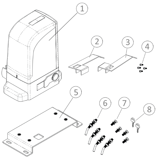
- Motorline Professional BRAVO 500 mechanism
- Left limit switch plate
- Right limit switch plate
- Screws for attaching limit switches to the rack
- Motor mounting base
- Foundation anchors for the mechanism base
- Screws for mounting the mechanism to the base
- Disengagement keys
Motorline BRAVO 500 Kit (Kit-Basic) - Contents

- Motorline BRAVO 500 mechanism with integrated Autotech S-5060T control unit and all its accessories (mechanism mounting base with mounting screws and anchors, limit switch activation plates, 2 manual release keys, detailed installation instructions in Greek)
- PSD-36T remote control, 1 pc
The above kit is typically used to replace a mechanism in an existing installation (it does not include a rack).
Criteria for choosing a sliding gate mechanism
The Motorline BRAVO 500 (Kit-Basic) sliding garage door opener kit is suitable for most garage doors. The data to be considered for selecting a sliding automation system are as follows:
- The weight of the garage door. The Motorline Professional BRAVO 500 mechanism can be installed on garage doors with a maximum weight of 500kg. This weight limit is sufficient for most cases, as an average door weighs 50-60kg/m. In most cases of residential or commercial doors, the above limit is sufficient. It is advisable to know the exact weight of the door from its manufacturer.
- The door's operating cycles per hour. The Motorline Professional BRAVO 500 mechanism is suitable for up to 14 operating cycles (openings/closings) per hour. This specification protects the motor from overheating. However, this should not concern the user as the motor has thermal protection. Thus, if it overheats, it will stop operating until the normal temperature is restored. It is logical that in a high-temperature environment, the motor's thermal protection will activate more easily than in a cold environment.
- The frequency of use per day. The motor's 30 uses per day are obviously considerably less than its capabilities. However, this is the optimal use for the motor to operate without problems for many years.
For the above measurements, a 5m door length was used as a reference. This door length is for calculation purposes and is in no way the maximum door length the motor can handle. The motor can be installed on any door length. It is self-evident that for shorter doors, the motor can operate with greater frequency per hour and day, while for longer doors, the opposite is true.
Dimensions of the Motorline BRAVO 500 sliding gate mechanism

Sliding garage door with mechanism - Features

Wiring for sliding mechanism and accessories

- The Motorline BRAVO 500 mechanism requires a 3x1.5mm² cable suitable for outdoor use. If the distance from the electrical panel is long, it would be advisable to use a 3x2.5mm² cable. In any case, it is good for the mechanism's wiring to start from a separate fuse in the electrical panel.
- Wired photocells require 4x0.6mm² cables for the receiver and 2x0.6mm² for the transmitter. If photocells with a reflector are used, only one 4x0.6mm² cable is required up to the transceiver. Reflector photocells cost a little more, but if the wiring has not been laid, they provide an immediate solution without repairs and extra work.
- The key switch (keypad) or simple push button requires a 2x0.6mm² cable.
- The warning light requires a 1x1.0mm² or 2x1.0mm² cable.
Wiring should be done by a qualified electrician. Particular attention must be paid to protecting the cables from moisture as these installations are outdoors.
Autotech S5060T control panel for sliding gate mechanisms

The Autotech S5060T control unit is included in the kit and is integrated into the mechanism. It is a control unit that combines simplicity of use with all necessary functions and has been time-tested. It works perfectly with the Motorline BRAVO 500 mechanism.
Technical characteristics:
- It has a socket for the mechanism's limit switches.
- We can adjust the mechanism's force.
- There is a possibility for soft start and stop for less wear and tear on the mechanism and garage door.
- It accepts safety photocells that interrupt movement when an obstacle is encountered during door closing and initiate reverse movement (opening).
- There is an available setting for automatic door closing with user-selectable closing start time. The use of photocells is essential for automatic closing to function.
- There is an option for electric braking.
- The opening direction is adjusted with a microswitch.
- The panel can accept a push-button (keypad or simple push-button).
- The panel can accept a 230VAC warning light without a flasher or a 230VAC lighting lamp.
- It has an integrated receiver with simple operation.
- User information regarding the mechanism's functions is provided by LED lights.
The above control unit has been tested by thousands of users and has proven to be extremely reliable. In addition, it features functions such as mechanism force adjustment, slow start and stop, which make it one of the best choices currently on the market.
ProfelmNet PSD-36T remote control for sliding gate mechanism

The ProfelmNet PSD-36T remote control is tested and reliable. It has 4 buttons to which we can set 4 different mechanisms (gate, shutters, overhead garage doors, etc.). It has a fixed 12-bit code at 433.92 MHz. It features a modern design and works exceptionally well with the Autotech S5060T control panel.
Sliding mechanism installation procedure - Summary
Briefly, the steps for installing a sliding garage door mechanism are as follows:
- Check that the door operates smoothly manually.
- Check the wiring if it exists or lay it.
- After the checks, the motor base is installed. It requires a stable foundation. Usually, a reinforced concrete base is the appropriate solution.
- Mounting the motor on the base.
- Installation of the rack.
- Installation of accessories (if any).
- Check for proper operation of the system and explain all details to users for safe use.
The above are just a brief overview of the steps for installing a sliding mechanism. Inside the mechanism's packaging, you will find detailed, step-by-step, well-written and easy-to-follow instructions.
Position of the Motorline BRAVO 500 sliding automation base
The base of the sliding garage door mechanism must be placed at a specific point for the motor to operate correctly. Below, the exact point where the base should be placed is defined, depending on whether the door opens to the right or to the left (left and right are defined as looking at the door from the side where the motor and rack are installed).


To find the correct position of the base, follow this procedure:
- Push the door leaf manually to the fully closed position. Place the mechanism base on the ground, at a distance of at least B from the edge of the door leaf.
- Push the door leaf manually to the open position. The base must be at distance C from the edge of the door. If this is true, the installation proceeds. If this condition is not met, there are 2 options:
- We compromise with the fact that the door leaf will not open completely (but will open up to the point where it reaches a distance C from the base). We choose this solution if the free opening is sufficient and what remains continues to meet our needs.
- We extend the door in length by extending the door leaf. It can be extended along its entire height or only at the point where it comes into contact with the rack.

The image shows the base and its mounting materials. The black plastic covers cover the mounting screws. The base has a hole for cable routing, which must be placed on the correct side.
Mechanism installation (height) - Detailed dimensions
The installation height of the mechanism is extremely important for the entire installation process. What matters is the height in relation to the rack for their proper cooperation. Often, the door design determines where the rack will be placed so that there are mounting points on the door for the rack. Below are detailed diagrams for the installation height of the mechanism for the case where the rack has been placed with the teeth downwards (this is the recommended and most common solution).


H1 = 38mm (height of motor mounting base)
H2 = 77mm (top of base to top of gear)
H3 = 15mm (top of gear to rack spacer axis)
H1+H2+H3=H4+H4+H5=130mm (bottom of base to rack spacer axis)
H4 = 72mm (top of base to bottom of rack)
H5 = 20mm (bottom of rack to rack spacer axis)
H6 = 10mm (spacer axis to top of rack)
H1+H4 = 110mm (bottom of base to bottom of rack)
Ho = height of raised foundation (the base can be placed in a raised position for spatial reasons). In this case, the motor is protected, e.g., in case of flooding.
Based on the above dimensions, a pre-check is performed before installing the mechanism. There are two cases:
- If a rack already exists, we check if its current height is suitable in relation to the mechanism's dimensions and the height at which its gear is positioned. If the dimensions do not match, we will either have to raise the mechanism's base (if the rack is high) or change the rack's position (uninstall and reinstall).
- If there is no existing rack, we check if there are available mounting points on the door for the rack at the desired installation height. Otherwise, we will have to place the entire structure higher by shaping the foundation on which the mechanism's base will be installed.
A crucial point of attention is the gap that must exist between the gear and the rack. Ideally, this gap should be 1.5mm.

If this gap does not exist, the mechanism is forced to carry the gate along its entire length of travel instead of simply pushing the gate. This will cause wear and tear and sooner or later problems will arise in its operation.
On the other hand, if the gap is too large, the cooperation between the gear and the rack will not be correct and jerks and stresses will be created on the motor. Therefore, special attention is required to create this gap.
Manual override of Motorline BRAVO 500 sliding gate mechanism

The manual override procedure for the Motorline BRAVO 500 mechanism is simple and easy for all users. With the key, open the disengagement door and push it to the fully open position. The garage door now operates manually. By reversing the procedure (closing and locking the door), we re-engage the mechanism.
Motorline Bravo 500 mechanism - gear

The Motorline Bravo 500 sliding gate mechanism features a high-strength metal gear. The cover protects against objects getting trapped between the gear and the metal rack. The protective cover is positioned in such a way that it allows the rack to be installed with the teeth facing upwards or with the teeth facing downwards.
Motorline BRAVO 500 sliding gate mechanism kit (Kit-Basic)
Installation instructions
The package you receive with the kit of your choice will include detailed instructions in Greek. The instructions have been thoroughly reviewed by our partners and have been translated into Greek in the best possible way. They are detailed and easy to follow.
The remote controls are configured and the kit is checked by our technicians. However, the instructions describe all installation steps in detail, in case you want to add new remote controls or change codes.
The instructions include detailed information on all stages of installing the mechanism's base, the rack, the mechanism itself, and the panel settings.
You can also download the instructions in English from the link below:
Bravo 500 mechanism instructions in English